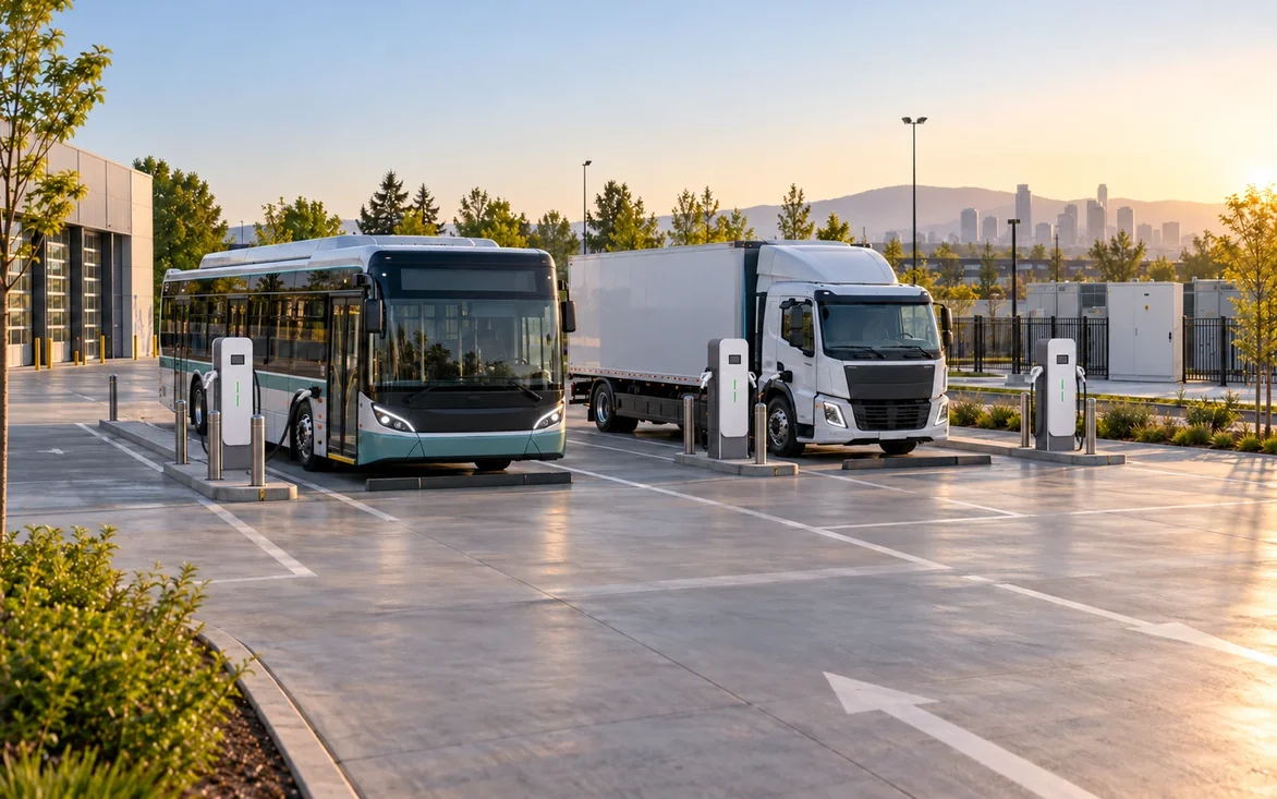
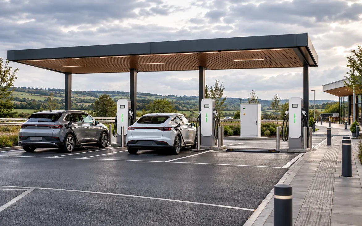
HIGH-POWER SPLIT CHARGING · 480–640kW
High-Power Charging Architecture for Buses, Heavy Trucks and Demanding Depots.
A centralized power system with remote dispensers for projects where higher charging power, multiple connectors and flexible site layout matter more than a conventional all-in-one charger.
SYSTEM OVERVIEW
Centralized Power for High-Energy Transport Charging.
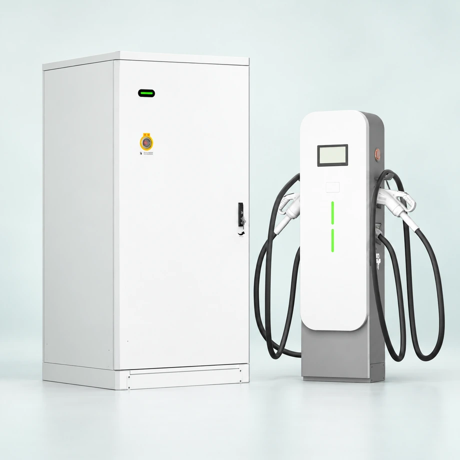
Split charging separates centralized power conversion from the vehicle interface. This architecture can support flexible dispenser placement, higher total site power and project-specific power allocation for bus, truck and demanding depot applications.
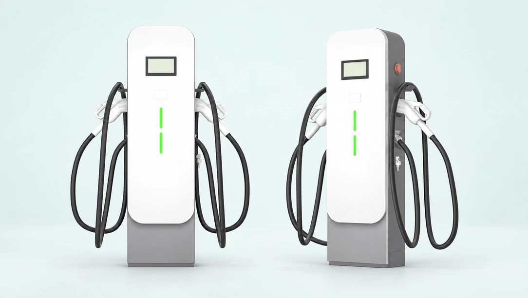
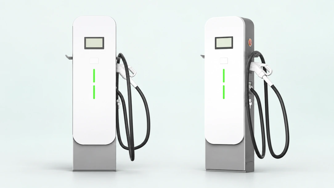
Architecture Highlights
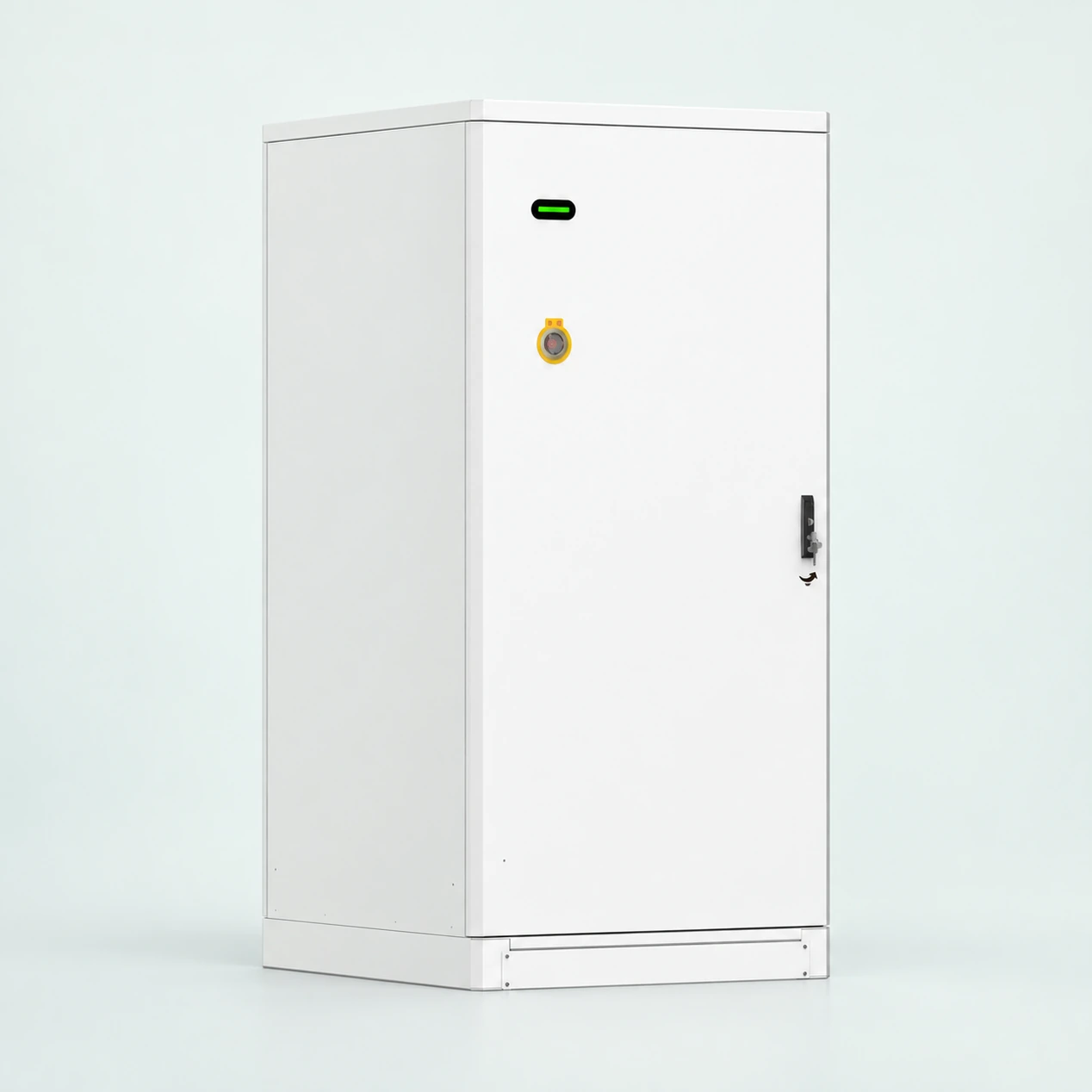
Centralized Power
The power system can be located away from the vehicle interface to support service access, site layout and distribution design.
Multiple Dispensers
One centralized power system can support multiple dispensers depending on the selected configuration and allocation logic.
480–640kW Range
The current portfolio scope covers high-power split systems in the 480–640kW class, with final architecture defined per project.
Split Charging Architecture
- 01Grid / Transformer
- 02Centralized Power Cabinet
- 03DC Distribution
- 04Remote Dispensers
- 05Bus / Truck / Fleet Charging Bays
Typical Applications
Bus Depots
For scheduled high-energy charging where multiple vehicles and fixed operating windows shape the design.
Heavy Trucks
For logistics and commercial transport applications that require higher charging power and engineered site layouts.
Large Fleet Sites
For depots where centralized power and multiple charging points may provide greater layout and power-allocation flexibility.
A System Project, Not a Commodity Charger.
For this power class, we first confirm vehicle charging capability, route or depot schedule, simultaneous charging demand, site electrical architecture, connector current, dispenser quantity and expansion plan before defining the system.
Technical Information
Choose the power cabinet and dispenser configuration as one system. Available power at each vehicle depends on cabinet capacity, dynamic allocation, output voltage, connector rating and vehicle demand. Specifications below refer to the May 2026 technical specification, revision 1.4.
Power Cabinet: 480kW vs 640kW
| Parameter | 480kW system | 640kW system |
|---|---|---|
| Rated system output | 480kW | 640kW |
| Maximum output channels | 8 | 10 |
| Dual-connector dispenser configuration | Up to 4 dispensers / 8 connectors | Up to 5 dispensers / 10 connectors |
| Single-connector dispenser configuration | Up to 8 dispensers / 8 connectors | Up to 10 dispensers / 10 connectors |
| Power conversion configuration | 12 × 40kW modules | 16 × 40kW modules |
| Maximum AC input current | 2 × 388A | 2 × 517A |
| Cabinet dimensions (W × D × H) | 1000 × 950 × 2050mm | 1000 × 950 × 2050mm |
| Weight, including power modules | 657kg | 721kg |
| Power distribution | Intelligent switching matrix dynamically allocates power modules across charging connectors | Intelligent switching matrix dynamically allocates power modules across charging connectors |
Electrical Performance
| Parameter | Specification |
|---|---|
| AC supply | 3-phase + N + PE; 380 / 400Vac ±10% |
| Input frequency | 45–65Hz |
| Power factor | >0.99 |
| Input current distortion (THDi) | <5% |
| Standby power | 70W |
| DC output voltage | 150–1000Vdc |
| Constant-power voltage range | 300–1000Vdc |
| System efficiency | >96.5% |
| Power cabinet interface | RGB status LED and emergency stop |
| Cabinet protection / noise | IP55 / ≤65dB |
Charging Dispensers & Cable Configuration
| Parameter | Specification |
|---|---|
| DC voltage range | 150–1000Vdc |
| DC bus inputs / output channels | 2 DC inputs / 2 output channels for the listed dual-connector dispensers |
| Dispenser current variants | 250A, 300A, 400A or 600A per output; the 600A variant uses liquid cooling |
| Listed dispenser output ratings | 2 × 250kW, 2 × 300kW, 2 × 400kW or 2 × 600kW, according to dispenser variant; these are terminal ratings, not simultaneous guaranteed system output |
| Connector arrangements | Single or dual connectors; CCS2, GB/T, CHAdeMO or supported mixed configurations |
| Connector-specific ratings | GB/T: 250A, with 300 / 400 / 600A options. CCS2: 250A, with 300 / 375 / 500A options. CHAdeMO: 150A. Confirm the exact cable assembly for the selected dispenser |
| Dimensions (W × D × H) | 500 × 350 × 1700mm, excluding cable retractors |
| Listed dispenser weight | 190kg; confirm the supplied cable and cooling configuration |
| User interface | 7-inch colour touchscreen, LED indicator, emergency stop and RFID |
| Cable management | Optional twin top-mounted cable retractors |
| Energy metering | DC meter compliant with JJG 1149-2018; MID-certified meter optional |
| Protection / noise | IP55; air-cooled dispenser ≤55dB; liquid-cooled dispenser ≤60dB |
Power and connector selection: all connectors share the cabinet’s 480kW or 640kW total capacity. A dispenser’s maximum rating is available only within the limits of the cabinet, voltage, cable and vehicle. Liquid-cooled output up to 600A is configuration-dependent. Confirm the connector-specific cable current in the final configuration; 600A is not a standard rating for every connector option.
Communication, Charging Control & Protection
| Parameter | Specification |
|---|---|
| Backend protocol | OCPP 1.6J or OCPP 2.0.1, depending on selected configuration |
| Connectivity | 100M LAN and LTE wireless modem support |
| Control capabilities | OTA updates, Plug & Charge, smart charging and power management support; availability depends on the selected hardware, firmware, vehicle and backend |
| Charging modes | Automatic, time-based, scheduled, energy-based (kWh) and state-of-charge (SOC) control; VIN and VIP identification support, subject to compatibility |
| GB/T vehicle communication | GB/T 27930-2023, with backward-compatibility support for earlier GB/T vehicles |
| Maintenance | Web / app maintenance backend, system self-diagnosis and maintenance alerts |
| Electrical protection | Input undervoltage, output overvoltage, short circuit, overtemperature, battery reverse connection, ground fault and insulation fault protection |
| Bidirectional option | V2G is listed as an option, with maximum discharge power of 480kW or 640kW respectively. Confirm availability, compatible vehicles, grid approval and project requirements before specifying |
Operating Environment
| Parameter | Specification |
|---|---|
| Operating temperature | −30 to +70°C |
| Full-power temperature limit | Up to +50°C; derating applies above +50°C. The technical specification states 5% per °C; confirm the configuration-specific derating curve during engineering |
| Transport / storage temperature | −40 to +75°C |
| Relative humidity | ≤95% RH, non-condensing |
| Altitude | 2000m |
| Atmospheric pressure | 80–110kPa |
Final configuration, cable current, local compliance, protection coordination and installation requirements must be confirmed in the project quotation and approved technical documents. Product specifications may change with development.
Documentation and Project Inputs
The technical information above defines the 480kW and 640kW cabinet options and the available dispenser configurations. Request the project-specific configuration sheet, installation drawings, cable schedule and applicable compliance documents before procurement. For project definition, share the vehicle type, charging capability, route or shift schedule, simultaneous demand, available site power and expansion plan.
System Datasheet
Verified power-system, dispenser and interface data for the selected split-charging configuration.
System Manual
Operating, safety and maintenance guidance prepared for the approved power and dispenser arrangement.
Installation & Commissioning Guide
Site, cabling, dispenser layout and commissioning guidance matched to the final system architecture.
Frequently Asked Questions
Why Use a Split Charging Architecture?
Separating the centralized power system from the vehicle interface can provide more flexibility for dispenser placement, service access and power allocation at high-energy transport sites.
How Many Dispensers Can One System Support?
The 480kW cabinet supports up to 4 dual-connector dispensers or 8 single-connector dispensers, for a maximum of 8 connectors. The 640kW cabinet supports up to 5 dual-connector dispensers or 10 single-connector dispensers, for a maximum of 10 connectors. Total power is shared dynamically; simultaneous vehicle output depends on voltage, cable ratings, vehicle demand and the selected allocation strategy.
What Information Is Needed for Depot Design?
Vehicle charging capability, battery size, route or shift schedule, simultaneous charging demand, connector current, site power and future fleet expansion are the key starting inputs.
Is 480–640kW Always Delivered to One Vehicle?
No. System power and per-vehicle output are separate design questions. Actual charging power depends on the vehicle, connector and the way total site power is allocated across active dispensers.
Related Solutions & Services